Product parameters
|
Item |
Specifications |
Unit |
||
|
Frequency Range |
fc |
100~3600MHz |
MHz |
|
|
Standard Frequency |
1575.42, 1582.4,1568,2655 |
MHz |
||
|
Useful Band Width |
3,25,48 or specify |
MHz |
||
|
Insertion Loss ( min) |
IL |
0.9,1.3,1.8, 2.2 or specify |
dB |
|
|
VSWR(max) |
2.0 |
dB |
||
|
Operating Temperature Range |
−40~+85 |
℃ |
||
|
Storage Temperature Range |
−40~+85 |
℃ |
||
Product Features
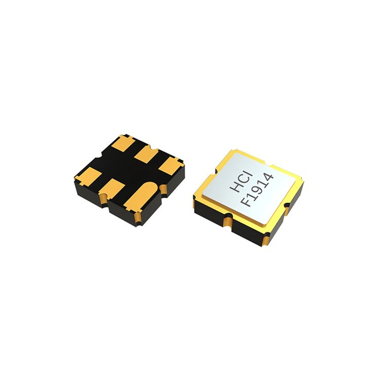
■ Small size 3.0x3.0x1.3mm
■ Welding can be done with automatic mounting
■ Low-loss SAW component
Applications
- The RF SAW Bandpass Filter 3 x 3 x 1.25 SF33M6 series is applied in Automotive Electronics, Low-Power Wireless Communication Devices, Communication Infrastructure and Consumer Electronics & IoT.


Product advantages
Low amplitude ripple
Sharp rejections at both out-bands
certificate
The RF SAW Bandpass Filter 3 x 3 x 1.25 mm-SF33M6 series is RoHS compliant.
FAQ
Q1: How to Verify the Performance of a RF SAW Bandpass Filter?
A: 1) Measure Insertion Loss (e.g., -1.5dB to -3dB typ. at center frequency) using a Vector Network Analyzer (VNA).
2) Characterize Bandwidth & Selectivity by plotting S21 to determine -1dB and -3dB bandwidths and out-of-band rejection (e.g., >25dB at ±100MHz offset).
3) Check Return Loss (S11/S22) to ensure impedance matching (e.g., >15dB) within the passband for minimal reflection.
Q2: Common Issues & Solutions for RF SAW Filter Integration?
A: Issue 1: Unexpected High Insertion Loss or Passband Ripple
Cause: Impedance mismatch between the filter and the surrounding PCB trace/component impedance (typically 50Ω).
Fix: Verify and adjust the input/output matching network (e.g., series or shunt inductors/capacitors) as recommended in the datasheet.
Issue 2: Poor Out-of-Band Rejection or Signal Leakage
Cause: EMI coupling from nearby interfering sources or insufficient grounding on the filter shield.
Fix: Ensure the filter's ground paddles are soldered properly to a solid RF ground plane. Use shielding cans and isolate the filter from noisy circuits (e.g., power amplifiers, clocks).
Hot Tags: rf saw bandpass filter 3 x 3 x 1.25, China rf saw bandpass filter 3 x 3 x 1.25 manufacturers, suppliers, High Frequency Saw Filter, Low Noise SAW Filter, RF SAW Bandpass Filter, RF SAW Bandpass Filter 3 X 3 X 1 25, SMD Low Pass SAW Filter 1 1x0 9x0 5, Wideband SAW Filter 3 8x3 8mm


